TECHNICAL TEASER
Do you have a Technical Teaser?
If you have a Technical Teaser that you would like to taunt our electrical colleagues with, then please send them in to us on email, fax, phone, letter.
April 2006 Teaser
QUESTION:
This teaser relates to Demand Side Management, and in particular:- RIPPLE CONTROL
Consider a set of water heaters (you know, the ones you use for showering) as seen from the supply side; i.e. the municipality’s side. When that set of water heaters is disconnected for a time by means of ripple control, then at switch-off there will be a fraction of water heater thermostat contacts closed; say 40%, i.e. 40% is the DIVERSITY factor, or fraction of the total set connected. This is called the AFTER DIVERSITY DEMAND in percent (ADD). Then if that set of water heaters is reconnected after an hour, then I’m sure you will agree that (definitely) more than 40% of the set’s contacts will be closed, as no more energy is pumped into the water-heaters. I.e. the ADD increases after a time period, and after a longer period of disconnection, the ADD will be even higher, and after a very long time of disconnection, then ALL 100% of water heaters’ thermostat contacts will be closed, i.e. ADD = 100%. So this is one of the tricks to DSM, to know what load is available, and how the ADD curves will behave as a function of SWITCH-OFF time.
Now for the question: Do the ADD time-constants change as a function of initial ADD?
Answer for April 2006 Teaser
To answer this question, Neil Jeffrey built a data logger in the late ‘seventies, and established some fascinating water-heater characteristics by measurement, whilst in Johannesburg City Power (then Jhb Electricity Dept). These curves had not yet been measured anywhere in the world, not even by Zellwegger Switzerland at that time.
The family of ADD curves were measured and plotted in a research project, the results (which Neil still has) makes really interesting reading. Initial ADD family curves were fed into a database of information, and plotted. Results are shown in the table below:
|
Initial After Diversity Demand |
TAU: Time constant of ADD curve [minutes] |
|
20-30% |
49 |
|
30-40% |
49 |
|
40-50% |
49 |
|
50-60% |
49 |
|
60-70% |
43 |
|
70-80% |
37 |
These results yield excellent fuel for the design of excellent ripple control strategies
(Watch the question next month, as it refers to what happens AFTER the water heaters are switched back ON after a time period)
March 2006 Teaser
QUESTION:
Is a transmission line more stable if it is running on NO load, light load, or a substantial load? Now I know this is not a very technical way to frame this discussion, but it could throw some light on the WCape / Gauteng power line problem that we have been experiencing recently!
Answer for March 2006 Teaser
Loosely speaking a transmission line that is under loaded, behaves similarly to a towed trailer that is not carrying any load i.e. it bounces around behind the car and is generally unstable. The moment a substantial load is placed into the trailer it becomes more stable and sits nicely behind the car. The transmission line from WCape to Gauteng is near a quarter wavelength, i.e. it takes about 5mSeconds for electricity to travel the distance. Quarter wave transmission lines behave in quite weird ways when they are not terminated in their characteristic impedance, especially when they are a quarter wavelength long. Open circuits appear as short circuits, and vice versa. Protection relay settings of the line need careful attention, as do compensation capacitors. We have simulated some of these transmission line characteristics and operating behaviours, which can lead to informed discussion.
January 2006 Teaser
QUESTION:
This is a holiday related question that has puzzled me over this past few weeks, and I do not know the answer!
1. How is it that monkeys can jump onto / into thorn trees with ease and great alacrity and not hurt themselves on the thorns
Answer for January 2006 Teaser
PLEASE, if there is anyone out there who knows the answer, then PLEASE tell me… I am fascinated!
I couldnt see if Google knows either?
October 2005 Teaser
QUESTION:
- Where is the highest electric field strength measured at 2m above ground level, under an overhead power line (which is 6m from ground)
a. Directly under the power line?
b. Two metres to the side?
c. Ten metres to the side?
- How can your answer be measured and verified
Answer for October 2005 Teaser
- Answer is b. because directly under the line, the three phases cancel each other’s electric field somewhat; and 10m to the side of the line, the electric field is quite low due to the high distance away
- You can measure this with SURETECH Instruments voltage sensors (HV/PA, HV/PT2, ODLLS, CLF, etc…)
September 2005 Teaser
QUESTION:
What is the a. electric field strength; and b. the magnetic field strength OUTSIDE the armouring of a MV cable?
Answer for September 2005 Teaser
- Electric field outside the armouring is zero as the lead / shield kills the field.
- Magnetic field close to the cable is measurable. The further one goes away from the cable, the closer the magnetic field disappears due to cancellation.
August 2005 Teaser
QUESTION:
Here’s the easiest question… everyone should get this one.
Of the electro-magnetic field around a wire carrying current, which parameter is associated with a. “electro”, and b. “magnetic”?
1. Power, 2. Reactive power, 3. Voltage, 4. Phase Angle, 5.Apparent power, 6. Current, 7. Power factor, 8. Something else
Answer for August 2005 Teaser
- Voltage
- Current
July 2005 Teaser
QUESTION:
- If you hold your hand NEAR a HV DC source (say 15kV DC), WITHOUT making physical contact to the HV DC conductor, can you become charged by the HV dc source?
- If you hold your hand NEAR the same HV DC source, does your hand feel a change in temperature?
- If so, higher or lower in temperature?
Answer for July 2005 Teaser
- Yes
- Yes
- It feels colder, we haven’t quite worked out exactly why; can anyone tell us why?
June 2005 Teaser
QUESTION:
A sheet metal plate has a circular cut-out 50mm diameter, and is earthed.
A pin is held at right-angles to the plate, with it’s sharp tip held at the centre of the 50mm hole
The pin voltage is raised, and so at what voltage will corona discharge first commence
Answer for June 2005 Teaser
ANSWER:
Corona will start to be notice-able at about 4kV rms, as one starts to hear faint crackling. If the voltage is raised to about 6kV, then it becomes very notice-able and you will hear a lot of crackling. By making the cut out ring smaller diameter, corona discharge will commence at a lower voltage (and vice-versa). Onset of corona discharge also depends on ambient pressure and humidity (This month we configured one of our SURETECH wideband capacitive voltage sensors to observe this type of corona, and individual discharge pulses are observable without making physical contact from a distance of about 100-150mm)
May 2005 Teaser
QUESTION: What is the B-H loop look like for an air-cored CT? ie. At what magnetic field strength does air saturate?
Answer for May 2005 Teaser
ANSWER:
This is the old class room question that we should have learned in 1st year physics, but most of us were sleeping in class on that day when it was told to us.
The constant of proportionality between B and H is u0 (mu zero), the permeability of free space, which is 4*PI*10-7 [Wb m-1 AmpTurn-1]
It is interesting to note that free space (including air and most plastics) exhibit the characteristic of not saturating under very high magnetic field conditions, and also do not exhibit hysteresis characteristics.
This characteristic is exploited in Rogowski coils, which exhibit extremely linear characteristics even at extremely high currents.
February 2005 Teaser
QUESTION: How hot is HOT? Can you tell how hot a plate is by touching it? How accurate can you get in degrees C? We humans have sensors that normally respond logarithmically to our environment; why don’t we have a scale of temperature that is orientated to us humans, after all, we have created a measurement scale of LUMENS for our EYES; and we have created the deci-BELL scale for measuring sound intensity for our EARS, and we have the Richter Scale that measures levels of vibration, so why not one for temperature: ANY IDEAS FROM YOU PEOPLE OUT THERE?
Answer for February 2005 Teaser
ANSWER:
Well? can you tell if your child has a “temperature” (is hot or cool), yes you can quite easily determine the difference between 37 and 41 degrees by feeling, just compare with your own body temperature
Hot bath water is over 50 degrees
If you can’t keep your hand for long on some metal part, it is most likely above 55-60 degrees.
I don’t have the answer for a logarithmic scale on temperature that is human related, so again I ask some of you bright sparks out there for some comment please?
January 2005 Teaser
QUESTION: What are the dimensions of electric field? Where is the highest electric field in a 3phase Medium Voltage power cable? What are the normal levels of electric field in these MV power cables.
Answer for January 2005 Teaser
ANSWER:
Dimensions of electric field: simple [Volts per meter]
Where is highest electric field in a 3phase cable: At
the interface of the semi-conductive screen of each MV conductor (ie the OD of
the MV conductor); the electric field is higher here than it is at the
semi-conductive screen on the OD of the insulation.
MV
cables are designed to run at around 7000 to 8000 Volts per mm electric field
strength. (i.e. high enough to break down in air!!!)
November 2004 Teaser
QUESTION: How does an LED (Light Emitting Diode)
work? Can a power diode (perhaps the common 1N4007) operate as an LED? If it
could generate light, would the light have a longer (eg infra-red) wavelength, or
a shorter (eg ultra-violet) wavelength than say a visible LED?
Answer for November 2004 Teaser
ANSWER:
Without going into the physics of how an LED works, very roughly it works like this: When a diode PN semiconductor junction (say silicon) has a forward voltage applied around 0.7Volts, electrons are raised in energy by this voltage and are elevated into higher energy orbitals around the nucleus. Electron energy level is related to the forward break-over voltage of 0.7Volts, and a dynamic equilibrium is set up between electrons that are raised to higher energy orbitals, and those electrons that return from the higher energy state to the lower energy state. When the electrons return to the lower energy state, energy is not lost, but rather the excess energy is given off as a photon of light energy, at a wavelength related to 0.7Volts; and this happens to be in the long wavelength Infra Red region of the light spectrum. So light IS given off in diodes, we just don’t see it due to the fact that we humans are blind to these wavelengths, and of course there is a covering over diodes that blocks the light. If we took the plastic or metal covering away from the diode, we would be able to detect the light if we had an appropriate Infra Red detector. The converse is also true, i.e. when we shine appropriate wavelength light onto a diode junction, we can generate electricity (although the transfer efficiency is very low)
For opto-isolators, the forward break-over voltage of the LED is about 1.1Volts, which results in higher energy (shorter wavelength light) than a common silicon rectifier at 0.7Volt. An opto-isolator diode buried inside a plastic chip inhibits light from escaping the package, and its LED light is directed at a corresponding transistor within the package that switches on when the LED current is sufficient. All transistors are also light sensitive, if we remove the packaging.
When it comes to visible light LEDs, the energy
levels are that much higher again, with a RED LED having a forward break-over
voltage of around 1.6Volts, and ORANGE LED having a forward break-over voltage
of 1.8Volts, and a BLUE LED having forward break-over voltage of 2.1Volts.
These devices can all generate these voltages if sufficient light is shone on
them at the corresponding wavelength.
October 2004 Teaser
QUESTION: What is the CRITICAL DIFFERENCE IN SAFETY
between using three single core MV armored cables, VS normal three core MV
armored cable to feed some MV plant such as a motor?
Answer for October 2004 Teaser
ANSWER:
The capacitance per meter of an armored three-core
cable is similar in value to the capacitance per meter of a single core armored
cable. The main difference between the 3-phase cable running at (say) 11kV line
and a single cored cable running at its phase voltage of 6350 Volts is that in
3-core cable, voltages all add up to ZERO within the cable. So, any individual
capacitive currents running into the armoring, which are contributed from each
of the phases, cancel each other out; this results in ZERO capacitive current
to earth. With this argument, we do of course assume balanced voltage
conditions.
So what happens when the voltage between phases is
not balanced? Then to the extent of imbalance, there will be a net capacitive
current that is set up in the armoring. If the imbalance in voltage is due to
say two phases being switched out while the third phase remains live, then a
high capacitive current will flow in the armoring. This condition is almost
identical to the single core cable carrying one phase.
Now, depending on the LENGTH of cable, this
capacitive current can easily be greater than 100mA for even short lengths of
cable. So, if the armoring is not earthed properly, then this represents a
SAFETY hazard for unsuspecting electrical workers and anyone else as well,
should they touch the armoring while they are earthed. Bear in mind that heart
fibrillation sets in at currents as low as 10 to 20mA, so 100mA is way higher
than this, and can easily kill someone.
September 2004 Teaser
QUESTION: What is the most important difference between an Earth Leakage Circuit Breaker installed in domestic environments (30mA tripping), and the Earth Leakage Relay installed in a factory set at (300mA) Hint, it is NOT the 30mA vs 300mA tripping level!!!
Answer for September 2004 Teaser
ANSWER:
30mA Earth Leakage Relays are specifically designed
to save peoples lives by tripping the CB when the difference between Live
current and Neutral current is greater than 30mA. A 300mA Earth Leakage Relay is
also designed to detect the difference between Live current and Neutral current
at a higher level, BUT DO NOT COUNT ON THE 300mA ELR TO SAVE YOUR LIFE, BECAUSE
HEART FIBRILATION STARTS AT AROUND 20mA OR SO!!! THE REAL DIFFERENCE IS
CENTERED ABOUT THE SAFETY OF PERSONNEL!!!
August 2004 Teaser
QUESTION: Harmonic analysis is becoming more and more important to electrical personnel; computers and UPS supported equipment are often a significant proportion of the load within some buildings.
- What are the predominant harmonics due to these types of loads ODD or EVEN harmonics
- Which order of harmonics have the largest amplitudes due to these type of loads: low order (< 8th harmonic) or higher order (> 8th harmonic)
Answer for August 2004 Teaser
ANSWER:
As more and more computer loads appear on the power system, they have the characteristic of drawing essentially the SAME current ALL of the time that they are operating. So when the sine voltage goes through zero, the computers are still demanding the same current at all points in the cycle. The switch mode power supplies in the computers will therefore adjust their operation to ride the sine voltage at all times of the cycle. The current drawn from the mains therefore tends to be SQUARE rather than SINE, and so its current components will therefore have predominantly ODD harmonics rather than EVEN. The LOW order harmonics will also tend to be higher than the higher order.
July 2004 Teaser
QUESTION: How many electrons pass by a given point during one second if ONE Ampere is flowing?
Answer for July 2004 Teaser
ANSWER:
One electron has charge of 1.602 x 10E-19 [Coulombs / electron]
So therefore 1 Coulomb has 1 / 1.602 x 10E-19 = 6.242 x 10E18 [electrons], OR 6.242 million, million, million [electrons]
And because 1 Amp is equivalent to 1 Coulomb per second,
Then the number of electrons passing a point in a circuit is this number
June 2004 Teaser
QUESTION: WHERE is the energy actually transported in an electrical circuit?
(a) the current in the conductor
(b) the voltage on the conductor
(c) both current in the conductor and voltage on the conductor
(d) somewhere else (explain)
Answer for June 2004 Teaser
ANSWER: There was only one person who ventured a correct answer, and that is Arthur Sadler, who used to work for us at SURE Engineering where he did his in-service training as a young technician, and is now working in the UK. Arthur’s mind is one of the quickest we have ever had the pleasure to work with; well done Arthur!
Of course the answer is not really associated with current or voltage, but rather the ELECTRO-MAGNETIC FIELD AROUND the cable. I.e. around the cable means at a distance from the surface of the cable; so it is in FREE SPACE where the energy is actually manifest, and is therefore transported through THAT space.
May 2004 Teaser
QUESTION: They tell us at university or college, that for fluid mechanics systems:
If the mass flow rate into a system EQUALS the mass flow rate out of the system, then there will be no build-up of matter / fluid in the system… agree??
Now in electrical systems Mr Kirchoff told us that the current in a series circuit is the same at all points in the circuit, i.e. flow rate of charge is the same going into a two terminal device, as it is going out. If this is the case with a capacitor charging up, then there must be a divergence between the fluid mechanics system and the electrical system, because the capacitor charges up in the electrical case to yield a voltage difference across the capacitor!!!!
Answers from you electrical people please, and we may even provide the person with the best answer, a prize of a SURETECH HV/PA the latest Personal Alert
Answer for May 2004 Teaser
ANSWER: From Kirchoff: current entering a capacitor in the one terminal equals the current leaving through the other terminal. So there is NO NET BUILDUP OF CHARGE IN THE CAPACITOR. The positive charge on the one plate is EQUAL to the negative charge on the other plate, and so both Mr. Kirchoff AND fluid mechanics can live (RIP) in harmony!
April 2004 Teaser
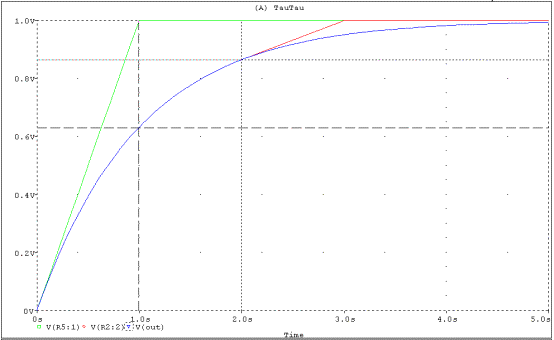
Is Tau really constant in an RC circuit?
After all if a capacitor has charged half way up, then how can its time constant be the same during the second half of charging?
Answer for April 2004 Teaser
Tau is Tau is Tau !!!!
A nice practical way to visualise the Time-constant of a circuit is to look at the exponential rise (or fall) of an RC circuit. If you draw a tangent to the exponential curve at the start of the curve, and extend this line straight through the asymptote (1.0Volt line); then the TIME difference between the start point, to the intersection point is 1 second in this example, ie. The time-constant.
If you started the exponential at the 2 second point (say), and drew the tangent to the curve there, then it still meets the asymptote 1second later at the 3second point, ie. After one time constant ( = 1 second in this example). This is simply one of the characteristics of exponentials.